Setting up a Drum Kit
If you have a GHWT or Band Hero Drum kit, you do NOT need to go down this method of hardwiring. The GHWT drum kits can be hardwired by connecting the microcontroller to the connector going to the brain, as there are just digital signals there and Santroller supports those signals.
Band Hero drum kits are modded a bit differently. If you open up the brain, you can remove the PCB with the microcontroller on it from the main PCB, then solder the replacement microcontroller to the I2C lines and the buttons directly to the microcontroller.I have not written documentation for either of these methods yet, but feel free to join the discord and ask for help, we can run you through how to do this there.
Supplies
-
A microcontroller
- Raspberry Pi Pico users: this legacy release does not support Pico boards. Use the currently supported Santroller tooling at santroller.com.
-
SparkFun Pro Micro (5V or 3.3V)
- The 3.3V version is easier to use with Wii and PS2 controllers. The 5V version requires voltage conversion for 3.3V peripherals.
-
Arduino Micro
-
Arduino Leonardo
-
Arduino Uno R1, R2, or R3
- The board must have the ATmega16U2 USB controller. Uno clones that use a CH340 USB chip are not supported.
-
Arduino Mega 1280, Mega 2560, or Mega ADK
-
An optional 4051 or 4067 based analog multiplexer if the microcontroller does not have enough analog inputs
- 74HC4051 / 74HC4067 parts are recommended, as they switch faster than CD4051B/CD4067B parts.
- The CD4051B/CD4051BE and CD4067B aren't recommended as they are slower parts
- However if you do get one of these, make sure to go for the slow multiplexer option when configuring, otherwise you will end up with drums reading inputs across multiple channels.
-
3.3V zener diode per drum / cymbal pad (if using a multiplexer)
- The multiplexers do not like high voltage spikes, and the zener diode will clamp them. Without this, you will get very messy readings when a drum is hit.
-
1MOhm resistor per drum / cymbal pad
-
Some Wire
-
Soldering Iron
-
Multimeter (it will be used mainly in continuity mode, where it beeps when the two contacts are shorted together)
-
Wire Strippers
-
Wire Cutters
-
Heatshrink
-
Supplies for specific features
- Drum kit from scratch
- 1 Piezo sensor per drum pad / cymbal
- Drum kit from scratch
Close the tool if you want to use your drum kit, the multiplexer is overridden by the tool when it updates its sensor values, and this will override the controller inputs when it happens.
Wiring Steps
Electronics basics
This guide assumes that you know how to solder. If you do not, stop now and go practice soldering.
If you have no idea what a microcontroller is, start here. If you are familiar with microcontrollers and PCBs skip to choosing a microcontroller.
A microcontroller is a small board that can be programmed to perform various functions. In this guide, you will be using the microcontroller to replace the main board of the guitar. Around the edge of the microcontroller, you will see various solder through-holes called pins. These are labelled with a pinout (which you can find by searching for your {your microcontroller} pinout) and sometimes on the microcontroller itself. The pins have various functions, but for this controller mod, you will need to be familiar with all 4 types of pins:
- GND (ground) - the common connection that all electrical components must connect to in one way or another in order to complete the circuit. Every set of functions for the guitar will feature a GND pin.
- VCC (common collector voltage) - this is where you would connect to provide power to a circuit. Sometimes this pin is labelled as 5V, 3.3V or 3v3 on the microcontroller or pinout.
- Digital Pins - These pins are the "basic" pins. They can essentially only show if a button is pressed or not pressed. You will use these for strum, start/select and frets. The are the most common pin on your microcontroller and are usually labelled with just a number.
- Analogue Pins - These pins provide a range of values rather than just on and off. These are the pins you will need to use for whammy, tilt (when using an accelerometer), or your joystick. Analogue pins are labeled on the pinout with A followed by a number.
Analogue pins can be used as a digital pin, but digital pins CANNOT be used as an analogue pin. So if it the instructions say connect to a digital pin, you can use an analogue pin.
Analogue pins can be used as a digital pin, but digital pins CANNOT be used as an analogue pin. So if it the instructions say connect to a digital pin, you can use an analogue pin. V<sub>CC</sub> and GND can have more than one wire soldered to them. For example, if you want tilt and whammy but only have one V<sub>CC</sub> you can solder them both to the single V<sub>CC</sub> pin on the microcontroller.
V<sub>CC</sub> and GND can have more than one wire soldered to them. For example, if you want tilt and whammy but only have one V<sub>CC</sub> you can solder them both to the single V<sub>CC</sub> pin on the microcontroller. Avoid pins 0 and 1 on the Arduino Uno, as these get used for sending controller information over USB.
If you are unfamiliar with microcontrollers, you may also be unfamiliar with PCBs in general and figuring out which pins correlate to which function. Here are some terms you will need to know.
- PCB (printed circuit board) - the often green or brown boards containing traces and electronic components
- Traces - the copper conductors on a board. They look flat and are often metalic. Think of them as "wires" on the board itself connecting components. If you are still confused, a quick google search can help you understand traces.
To keep the relevant information in this guide easy to find, information is sorted by function.
Face buttons
- Trace the pads on the drum PCB that contains the face buttons. The face buttons should have a common ground, you should see this as a trace that connects multiple buttons together. Find some way to connect a wire to this, if there is a test pad or something you can solder to, solder your wire to that, otherwise you will need to scrape back one of the traces with a knife so you can solder to that. Solder this to ground on your microcontroller.
- Follow the traces for the other side of each button, and solder a wire to them in a similar way as the common wire. Then solder that to a digital pin on your microcontroller.
Multiplexer
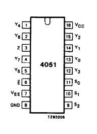
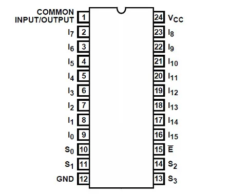
- Wire VCC on the multiplexer to VCC on the microcontroller.
- Wire VSS to GND on the microcontroller.
- If your multiplexer has a VEE, also wire that to ground. VEE allows for using the multiplexer with negative voltages, but since we aren't doing this we set it to ground to disable that feature.
- Also wire INH / Inhibit to ground, if this exists on your multiplexer. This pin disables the I/O if it is driven high, so we ground it to make sure the chip is always enabled.
- Wire the analog output (often labelled COM, common in/out, or SIG) on the multiplexer to an analog pin on your microcontroller.
- Wire A/S0, B/S1 and C/S2 (and D/S3 for the 16 channel multiplexer) to separate digital pins on your microcontroller.
- Wire each drum pad to a different channel on the multiplexer.
Drum / Cymbal pads
Note that the piezo is directional and does need to be wired in the correct way. If it doesn’t work, swap the wires around.
- Disconnect the piezos from the main drum PCB.
- Solder the black wire from the piezo to ground.
- Solder the red wire to an analog input on the multiplexer / micocontroller.
- Solder a 1Mohm resistor between the analog input your piezo is connected to on your multiplexer / microcontroller and ground
- Solder a diode between the analog input your piezo is connected to on your multiplexer / microcontroller and ground
RB Pedal
- The pedal connector has two wires coming out of it. Connect one to ground and one to a digital pin on your microcontroller.
GH Pedal
- Solder the one wire from the pedal connector to ground.
- Solder the other wire to an analog input on the multiplexer, or directly to an analog pin on your microcontroller if it has enough analog pins.
- Solder a 1Mohm resistor between the two wires on the pedal connector.
Programming
-
Start Santroller with your microcontroller plugged in.
-
Set the Input Type to Directly Wired
-
Click on
Configure -
Click on
Controller Settings -
Set
Emulation TypetoControllerfor standard guitars andFortnite Festivalfor Fortnite Festival. -
Set the
Controller Typebased on the game you want to play. -
Windows controller modecan be set based on your preferences. Note that this is only for Windows, no other operating systems or consoles will be affected by this option.XInput- This works more natively on windows, and most games will automatically bind controls.HID- This uses HID on windows, which means games won't automatically bind controls, but HID is polled a bit more efficiently in games like Clone Hero.
-
If you would like to adjust settings related to polling, click on
Controller Poll Settings -
Set the Poll Rate to your preferred setting. 0 sends data as fast as possible, any other number polls inputs at that speed.
-
Debounce can be adjusted here. You will need to increase this, as debounce sets the minimum time for a drum hit, and this will turn the drum hit that only occurs for a few microseconds into a signal that the game expects. While testing I used a debounce of 20ms but you will have to adjust this to find a value that works for you. The main thing to consider is that it takes a bit of time between you going to hit a drum pad and you hitting the pad, so if the debounce is too low, you may just miss drum hits due to the note not being on for long enough.
-
Now you can start setting up your inputs. To keep this information relevant, it is grouped by function.
Face buttons / RB Pedal
- Click on the button you want to configure, and make sure the
Input Typeis set toDigital Pin Input. - Make sure
Pin Modeis set toPull Up. - Click on the
Find Pinbutton, and then press the button on the guitar. If you have wired everything correctly, the tool should detect the pin and the icon for that button should now light up whenever the button is pressed.
Drum / Cymbal pads / GH Pedal (Multiplexer)
- Click on the drum pad in question
- Set the
Input Typeto multiplexer - Set the S0, S1, S2 (and S3 for a 4067 based multiplexer) pins
- Set the analog output / SIG / COM pin to the analog pin you wired it to
- Hit the drum pad in question. You should see the raw value for the drum pad change.
- Hit the pad lightly, and drag the minimum up so that it registers small hits.
- Hit nearby pads and make sure that the vibrations from those pads don't activate the pad you are configuring. If they do, then increase the minimum. You should end up with each pad registering hits, without crosstalk or needing to hit the pads too hard.
Drum / Cymbal pads / GH Pedal (Direct analog)
- Click on the drum pad in question
- Set the
input typetoAnalog Pin Input - Click on
Find Pinand then hit the drum pad in question, it should detect the drum that was just hit. - Hit the drum pad in question. You should see the raw value for the drum pad change.
- Hit the pad lightly, and drag the minimum up so that it registers small hits.
- Hit nearby pads and make sure that the vibrations from those pads don't activate the pad you are configuring. If they do, then increase the minimum. You should end up with each pad registering hits, without crosstalk or needing to hit the pads too hard.
- Click on the button you want to configure, and make sure the