Setting up an Adapter for a Wii Controller
This guide walks through the hardware and software setup required to use a Wii controller extension with Santroller.
Supplies
Required
-
Microcontroller
- Raspberry Pi Pico users: this legacy release does not support Pico boards. Use the currently supported Santroller tooling at santroller.com.
-
SparkFun Pro Micro (5V or 3.3V)
- The 3.3V version is easier to use with Wii and PS2 controllers. The 5V version requires voltage conversion for 3.3V peripherals.
-
Arduino Micro
-
Arduino Leonardo
-
Arduino Uno R1, R2, or R3
- The board must have the ATmega16U2 USB controller. Uno clones that use a CH340 USB chip are not supported.
-
Arduino Mega 1280, Mega 2560, or Mega ADK
-
Wii Extension breakout board or extension cable
- Example: Adafruit Wii Nunchuck Breakout Adapter
- You may also cut the end off an extension cable and solder directly if preferred
-
Wire
-
Soldering iron
Power considerations
- If your Wii Extension breakout does not support 3.3V input and you are using a 5V microcontroller, you will need a 3.3V voltage regulator
- The Adafruit breakout linked above supports both 3.3V and 5V input and does not require an external regulator
Optional features
Tilt support
Any of the following options are supported:
-
Digital tilt switch (sometimes called a mercury or ball tilt switch)
- Using two tilt switches in series is recommended to reduce accidental activations
-
Digital accelerometers: ADXL345 or LIS3DH
- Provides analog acceleration data
- Tilt is detected using acceleration due to gravity
- While the MPU-6050 is supported, it has been obselete for years now, and thus most MPU-6050s that can be purchased are fakes and the fake units have many issues, so it is recommended to stay away from them.
-
Analog accelerometers: ADXL335 or accelerometers found in some Guitar Hero guitars
- Provides analog acceleration data
- Tilt is detected using acceleration due to gravity
Never supply 5V power to the power pin of a Wii Extension. Wii Extensions are not designed for 5V input.
The data pins are 5V tolerant and may be connected directly to microcontroller GPIO pins.
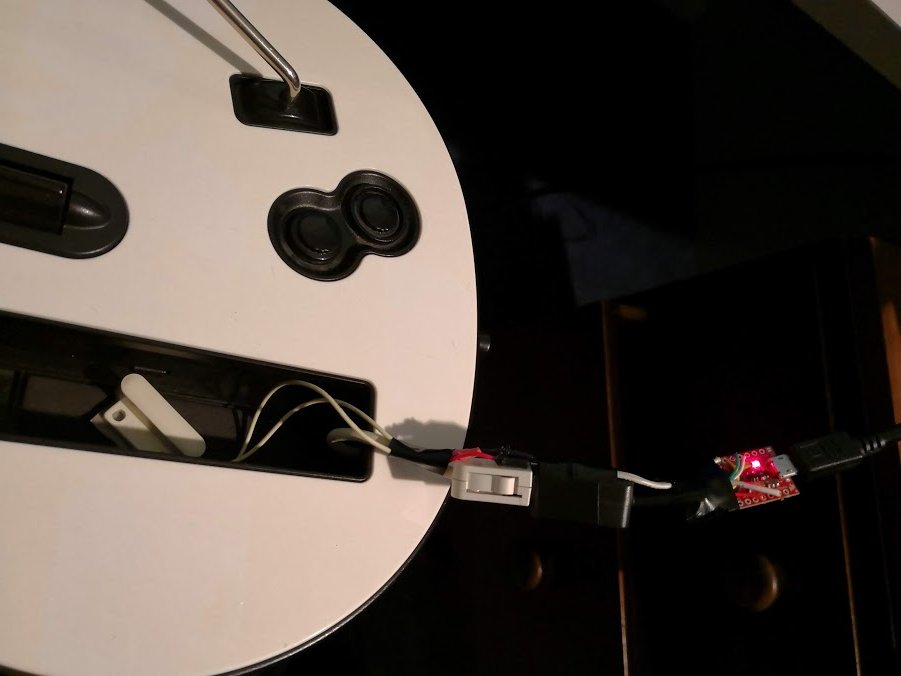
Finished product
Wiring steps
1. Connect SDA and SCL
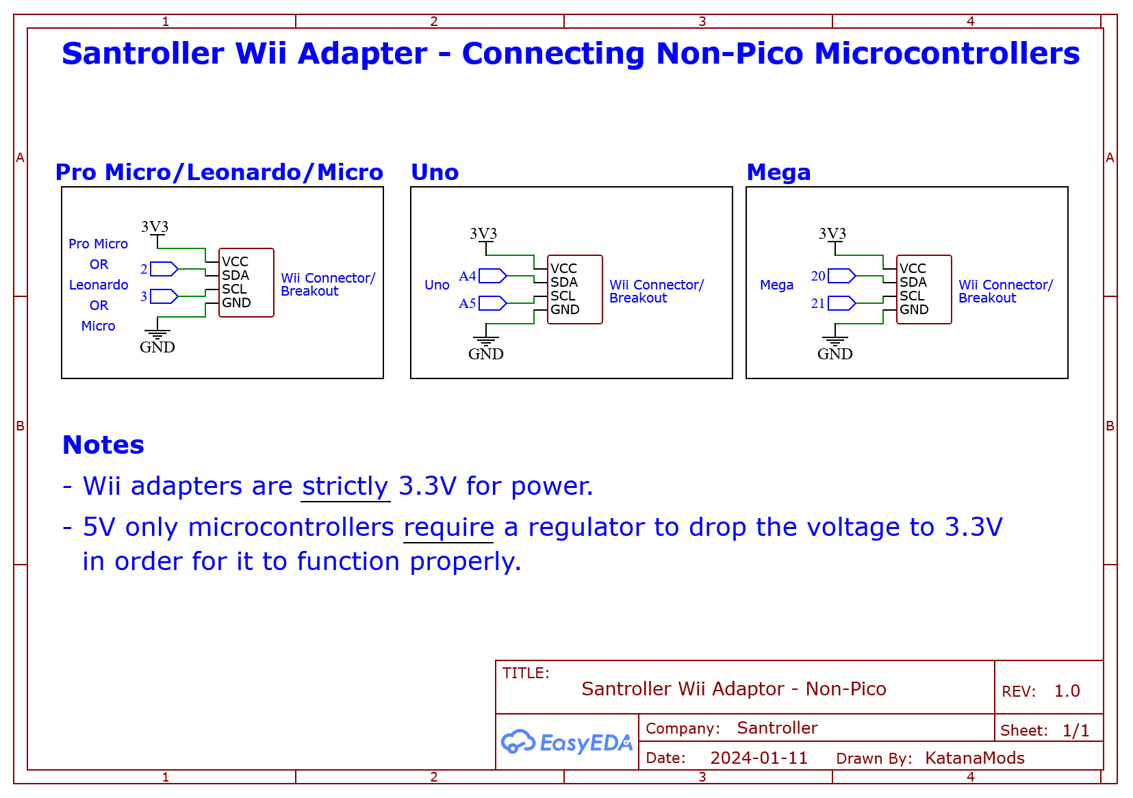
Connect the SDA and SCL pins from your Wii Extension breakout or extension cable to your microcontroller.
Refer to the image below for the Wii Extension connector pinout.
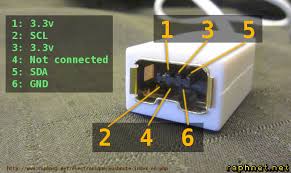
If you are using a Wii Extension cable, do NOT rely on wire colors.
Manufacturers use inconsistent coloring. Always verify each wire using the pinout above. Some cables have been observed with green as ground and black as 3.3V.
| Microcontroller | SDA | SCL |
|---|---|---|
| Pro Micro / Leonardo / Micro | 2 | 3 |
| Uno | A4 | A5 |
| Mega | 20 | 21 |
2. Connect power (VCC)
- Connect the microcontroller VCC to the breakout VCC
- If using a 5V Pro Micro and a breakout that does not support 5V input, route VCC through a 3.3V regulator
- On the Arduino Uno, use the onboard 3.3V pin
- On the Adafruit breakout:
VINaccepts both 3.3V and 5V input- The
3Vpin is an output and is not required
3. Connect ground
Connect GND on the Wii Extension breakout or cable to GND on the microcontroller.
4. Optional: tilt wiring
Digital tilt
- Connect one pin of the first tilt switch to ground
- Connect the other pin of the first switch to one pin of the second switch
- Connect the remaining pin of the second switch to a digital input on the microcontroller
- Mount the switches on the guitar and adjust placement to control activation angle
Analog tilt
- Connect GND to GND
- Connect VCC to VCC
- Connect the signal pin to an analog input
ADXL345 / MPU-6050 / LIS3DH
- Connect GND to GND
- Connect VCC to 3.3V (use a regulator if required)
- Connect SDA and SCL using the table above
Programming
- Launch Santroller with the microcontroller connected
- Set Connection Method to
Wii Adapter - Set Device to Emulate to the desired controller type
- Click Configure
- Click Save Settings
Windows controller mode
This setting only affects Windows behavior. Consoles and other operating systems automatically select the correct mode.
-
XInput
- Native Windows support
- Most games auto-bind controls
-
HID
- No automatic binding
- Slightly more efficient polling in games like Clone Hero
Polling and debounce
- Controller Poll Settings allows adjustment of polling behavior
- Queue Based Inputs queues inputs internally and sends them at the USB maximum rate (1 ms)
Poll rate settings:
0sends data as fast as possible- Any other value polls at the specified rate
- DJ Hero turntables must use a poll rate of 10
Debounce:
- Filters noisy button signals
- Prevents dropped sustains caused by button bounce
Combined strum debounce (guitars only):
- Shares debounce timing between strum up and strum down
- Prevents rebound-triggered extra strums
Wii Extension inputs
- Open Wii Extension Inputs
- Click Save
Calibration
Use the Wii Inputs to display below dropdown if multiple devices are connected.
Joysticks / crossfader
- Click Calibrate and move fully left or up
- Click Next and move fully right or down
- Click Next and move slightly off center to set the deadzone
Whammy bar
- Click Calibrate
- Release the whammy and click Next
- Fully press the whammy and click Next
- Release again and click Next
Turntable spin
- Adjust the multiplier if responsiveness is too low
Configuring tilt in Santroller
Ensure you are emulating a guitar, then click Add Setting and add Tilt.
Digital tilt
- Set Input Type to
Digital Pin Input - Set Pin Mode to
Pull Up - Click Find Pin and tilt the guitar
- Enable Invert if using an inverted-output sensor such as some SW520D variants
Analog tilt
- Set Input Type to
Analog Pin Input - Click Find Pin and tilt the guitar
- Click Calibrate
- Tilt down and click Next
- Tilt up and click Next
- Hold the resting position and click Next
Accelerometer-based tilt
- Click Add Setting and add Accelerometer
- Click Save
- Set Input Type to
Accelerometer Input - Click Calibrate
- Hold the resting position and click Next
- Tilt up and click Next
- Tilt slightly upward and click Next to set the deadzone
- Adjust the Low Pass Filter
- Values near 0 reduce shake sensitivity but lower responsiveness
- Values near 1 increase responsiveness but amplify noise
- A starting value of 0.05 is recommended