Setting up a Guitar
Wiring
Supplies
-
A microcontroller
- Raspberry Pi Pico users: this legacy release does not support Pico boards. Use the currently supported Santroller tooling at santroller.com.
-
SparkFun Pro Micro (5V or 3.3V)
- The 3.3V version is easier to use with Wii and PS2 controllers. The 5V version requires voltage conversion for 3.3V peripherals.
-
Arduino Micro
-
Arduino Leonardo
-
Arduino Uno R1, R2, or R3
- The board must have the ATmega16U2 USB controller. Uno clones that use a CH340 USB chip are not supported.
-
Arduino Mega 1280, Mega 2560, or Mega ADK
-
Some Wire
-
Soldering Iron
-
Multimeter (it will be used mainly in continuity mode, where it beeps when the two contacts are shorted together)
-
Wire Strippers
-
Wire Cutters
-
Heatshrink
-
Supplies for specific features.
- Tilt
- Any of the following options are supported.
- A Digital Tilt Switch (somtimes called a mercury or ball tilt switch)
- It is recommended using two tilt sensors in series, as this can help with accidental activations.
- An ADXL345 or LIS3DH Accelerometer.
- Gives a proper analog value of the devices acceleration.
- Tilt is detected by observing acceleration due to gravity.
- While the MPU-6050 is supported, it has been obselete for years now, and thus most MPU-6050s that can be purchased are fakes and the fake units have many issues, so it is recommended to stay away from them.
- Gives a proper analog value of the devices acceleration.
- An analog accelerometer, such as the ADXL335, or the accelerometer on certain GH guitars.
- This gives a proper analog value of the devices acceleration
- Tilt is detected by observing acceleration due to gravity
- This gives a proper analog value of the devices acceleration
- A Digital Tilt Switch (somtimes called a mercury or ball tilt switch)
- Any of the following options are supported.
- Guitar Hero World Tour Guitar
- MPR121
- Required for reusing the slider bar from a Guitar Hero World Tour Guitar.
- MPR121
- Guitar Hero 5 Guitar or Crazy Guitar
- Standard Mode, worst latency.
- No extra parts required.
- MPR121 Mode, great latency
- Requires a MPR121, replaces the microcontroller on the slider bar and handles both slider and frets.
- Hardwire frets, great latency.
- No extra parts required, but sacrifices the detachable neck.
- Standard Mode, worst latency.
- Tilt
Wiring Steps
Electronics basics
This guide assumes that you know how to solder. If you do not, stop now and go practice soldering.
If you have no idea what a microcontroller is, start here. If you are familiar with microcontrollers and PCBs skip to choosing a microcontroller.
A microcontroller is a small board that can be programmed to perform various functions. In this guide, you will be using the microcontroller to replace the main board of the guitar. Around the edge of the microcontroller, you will see various solder through-holes called pins. These are labelled with a pinout (which you can find by searching for your {your microcontroller} pinout) and sometimes on the microcontroller itself. The pins have various functions, but for this controller mod, you will need to be familiar with all 4 types of pins:
- GND (ground) - the common connection that all electrical components must connect to in one way or another in order to complete the circuit. Every set of functions for the guitar will feature a GND pin.
- VCC (common collector voltage) - this is where you would connect to provide power to a circuit. Sometimes this pin is labelled as 5V, 3.3V or 3v3 on the microcontroller or pinout.
- Digital Pins - These pins are the "basic" pins. They can essentially only show if a button is pressed or not pressed. You will use these for strum, start/select and frets. The are the most common pin on your microcontroller and are usually labelled with just a number.
- Analogue Pins - These pins provide a range of values rather than just on and off. These are the pins you will need to use for whammy, tilt (when using an accelerometer), or your joystick. Analogue pins are labeled on the pinout with A followed by a number.
Analogue pins can be used as a digital pin, but digital pins CANNOT be used as an analogue pin. So if it the instructions say connect to a digital pin, you can use an analogue pin.
Analogue pins can be used as a digital pin, but digital pins CANNOT be used as an analogue pin. So if it the instructions say connect to a digital pin, you can use an analogue pin. V<sub>CC</sub> and GND can have more than one wire soldered to them. For example, if you want tilt and whammy but only have one V<sub>CC</sub> you can solder them both to the single V<sub>CC</sub> pin on the microcontroller.
V<sub>CC</sub> and GND can have more than one wire soldered to them. For example, if you want tilt and whammy but only have one V<sub>CC</sub> you can solder them both to the single V<sub>CC</sub> pin on the microcontroller. Avoid pins 0 and 1 on the Arduino Uno, as these get used for sending controller information over USB.
If you are unfamiliar with microcontrollers, you may also be unfamiliar with PCBs in general and figuring out which pins correlate to which function. Here are some terms you will need to know.
- PCB (printed circuit board) - the often green or brown boards containing traces and electronic components
- Traces - the copper conductors on a board. They look flat and are often metalic. Think of them as "wires" on the board itself connecting components. If you are still confused, a quick google search can help you understand traces.
For every function of the guitar, you will follow these same 3 basic steps. More details for specific functions will be given below.
- Find out what each pin correlates to on the exsisting components in the guitar. (AKA work out the pinout) In some guitars, all of the pins are labeled on the main board or other various pcbs, sometimes on the bottom of the main board.
- Cut the wires away from the main board as close to the PCB as you can, giving yourself the most amount of wire that you can get. You may find however that the wire isn't long enough, in this case you can either join some more wire onto the end of the existing wires or you can desolder the cables and replace them.
- Connect the wires to appropriate pins on the microcontroller.
Once you have successfully modded one guitar (or even during your first) you will find it easiest to disconnect everything then begin soldering as it gives you more room to work. To keep the relevant information in this guide easy to find, information is sorted by function.
Start and Select
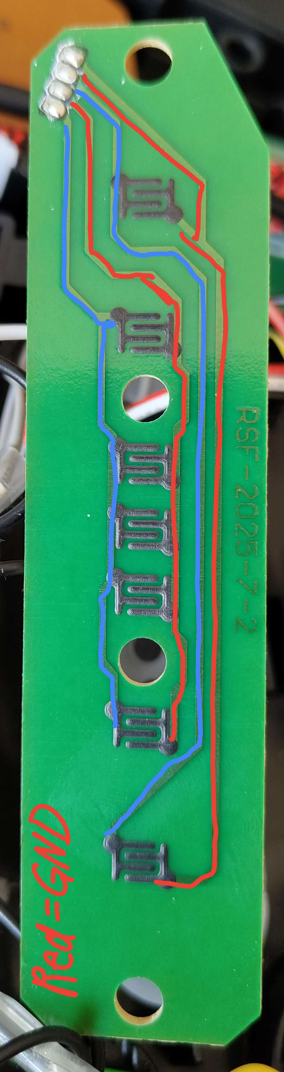
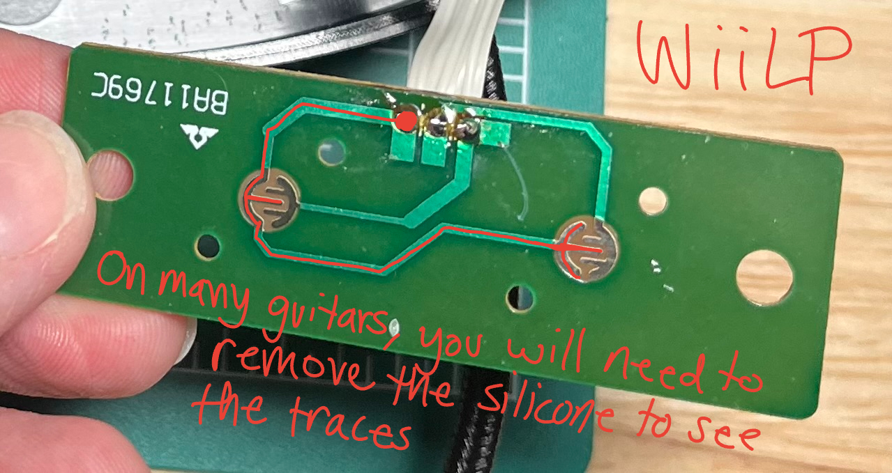
- If it is not labeled on the motherboard, you need to figure out which pin (or pins) is GND. If you remove the membrane, you will be able to see which pin connects to both start and select by following the traces - that pin is GND. (if there are multiple "grounds" they may be labeled as col, or column) Marking GND with a sharpie or using a differently colored wire is reccomended. If you are still unsure, the multimeter can help you confirm if you have the wires correct, as it will beep when you click a button and have the correct wires. There are examples of the 360 WT and WiiLP above.
- Connect the common ground to a GND on the microcontroller. If there are two ground wires, you can twist them together and put them in one ground pin on the microcontroller. This will sometimes be necessary when using a microcontroller that has a smaller number of pins.
- Connect each button to an unused digital pin on the microcontroller.
To wire an xplorer start/select board you will have to solder directly to the contacts and cut the traces that connect to each contact. It is not recommended you try to mod an xplorer as your first project because this can be difficult.
Whammy
- With most whammy bars, there are 3 pins. (if there are 4, you do not need the fourth. 2 pins is discussed below) The middle pin is the data pin, one outer pin is VCC while the other pin is GND (it doesn't matter which one, you can flip it when programming later if needed). Whammy needs to go to an analogue pin.
- Connect VCC and GND to the microcontroller. (the two outside wires)
- If your whammy isn't responding properly in game, you may need to swap VCC and GND around.
- Connect the data (middle) pin to an analogue pin on the microcontroller. These are labeled with an A on the microcontroller.
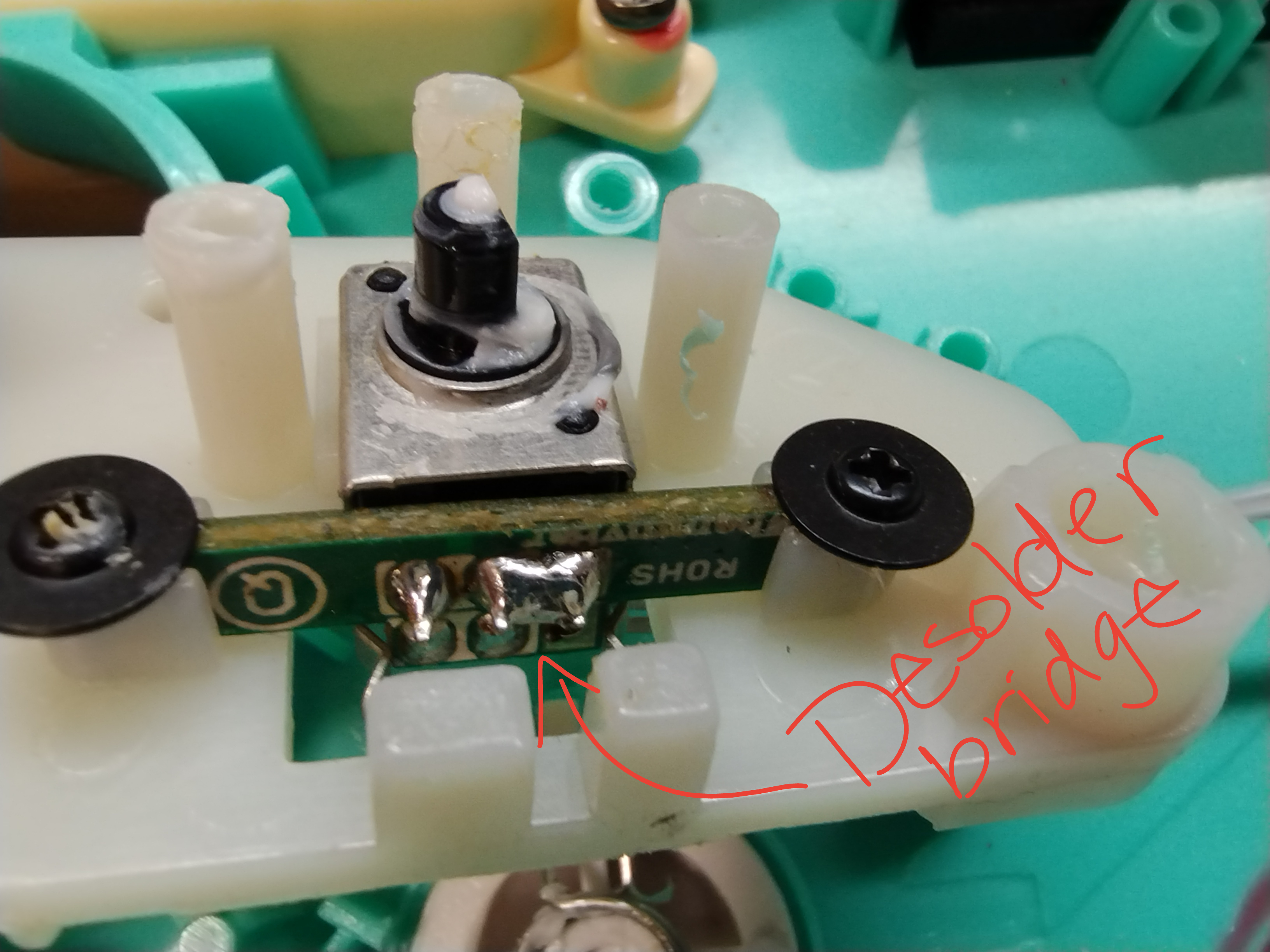
If you are working on a controller with only "2" pins as shown below, you will need to desolder the bridged pins and run 3 wires yourself as noted above for the whammy to work best with the configurator.
Pickup Selector
- With most pickup selectors's there are 3 pins. (if there are 4, you do not need the fourth. 2 pins is discussed below) The middle pin is the data pin, one outer pin is VCC while the other pin is GND (it doesn't matter which one, you can flip it when programming later if needed). Whammy needs to go to an analogue pin.
- Connect VCC and GND to the microcontroller. (the two outside wires)
- If your whammy is not responding correctly in game, you may need to swap VCC and GND around.
- Connect the data (middle) pin to an analogue pin on the microcontroller. These are labeled with an A on the microcontroller.
If you are working on a controller with only "2" pins as the RB Precision Bass, you will need to desolder the bridged pins and run 3 wires yourself as noted above for the pickup selector to work best with the configurator. For the Precision Bass this is easiest done by desoldering the PCB attached to the potentiometer, and then running your own wires directly to the potentiometer.
Digital Tilt
- Connect one pin of the first tilt sensor to ground
- Connect the other pin of the first tilt sensor to a pin on the second tilt sensor
- Connect the other pin of the second tilt sensor to a digital pin on your microcontroller.
- Affix the sensors to your guitar. You will need to play around with their position to get them to activate at the exact point you want tilt activating.
Analog Tilt
- Connect GND to GND
- Connect VCC to VCC
- Connect the signal pin to an analog pin on your microcontroller
ADXL345 Or MPU 6050 or LIS3DH
-
Connect GND to GND
-
Connect VCC to VCC (note that this is a 3.3v device, so for 5V microcontrollers make sure your breakout has a voltage regulator onboard or you are using your own regulator)
-
Hook up SDA and SCL to the microcontroller
Microcontroller SDA SCL Pro Micro, Leonardo, Micro 2 3 Uno A4 A5 Mega 20 21
Joystick (or DPad)
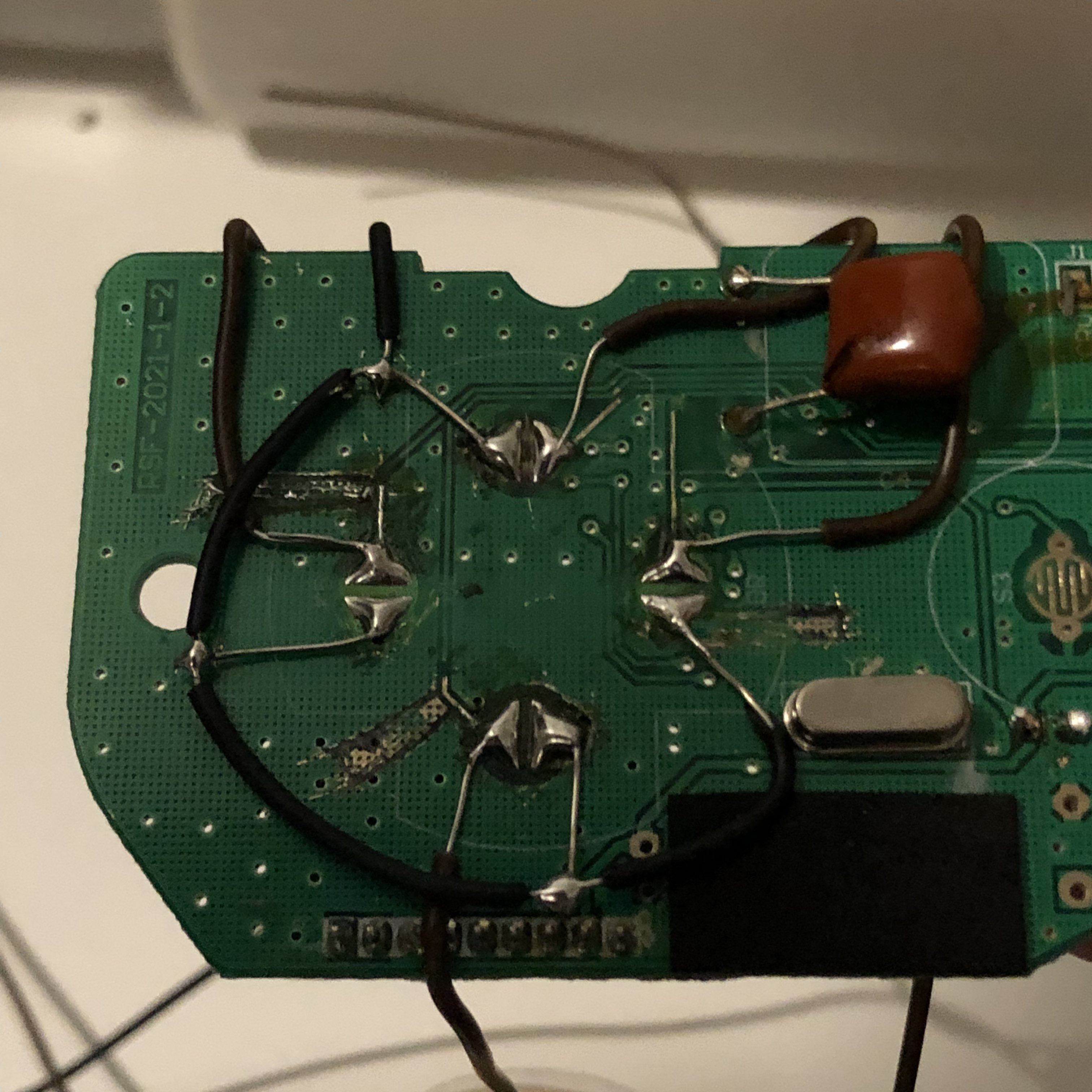
For d-pads that are integrated with the main board it is advised you skip wiring the dpad as you have to solder directly to the contacts and run wires accross the board. You will either be able to use your keyboard for these buttons, or they really won't really be needed as the games were designed to be controlled with the guitar alone. Below is an example of what this can look like, and why it is advisable to skip.
For guitars with a DPad that is seperate, it will be much easier to wire as you can follow the traces and wire it to the pins like you would for start/select.
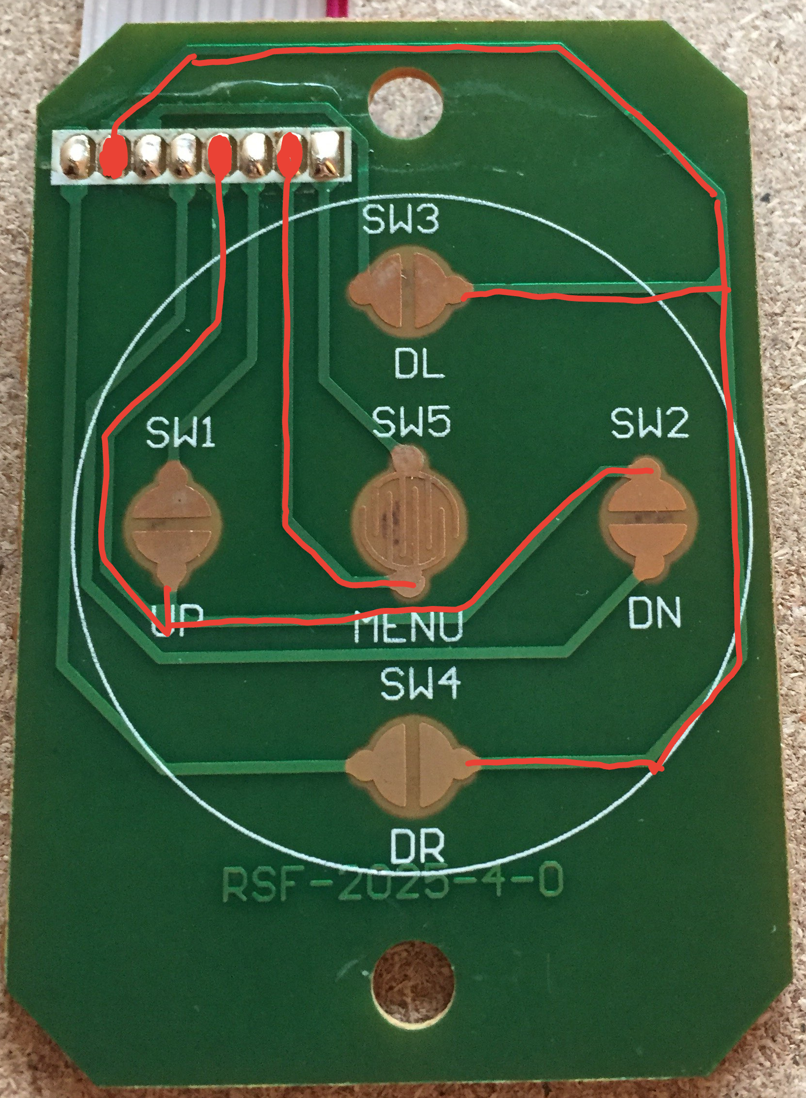
- Find ground. There will be a single common ground and a pin for each direction or multiple "grounds" depending on the model. (some may once again be labeled as col or column) Just like for start and select, you will need to follow the traces to figure out which pin is GND. Mark GND, then connect it to a GND pin on the microcontroller. If there are more than one ground wires, you can twist them together and combine them again.
- Up and down on the dpad MUST be connected to the same pins you will be using for strum. You will want to twist those wires together and solder them to the same pin. You may want to wait until you are working on the strum to connect these pins.
- Home, left, and right can be connected to any unused digital pin on the microcontroller.
For guitars with a joystick, there will be four pins, one is VCC, one is GND, one is the x axis and one is the y axis. You can work out which is which by tracing the traces, however on some guitars the traces are labelled for you. The joystick needs to go to an analogue pin (one of the A pins)
Frets
- For the frets, if it is not labeled it is easiest to open up the neck and follow the traces between the fret contacts. The ground wire traces will connect to all of the fret contacts, whereas a fret trace will lead to a single fret contact. If using the multimeter, test between the fret wire and the ground wire, and the multimeter should beep when the fret is pressed.
- Connect the common grounds to a ground pin on the microcontroller.
- Connect each fret to its own unused digital pin.
RB Frets
With some RB guitars, the solo frets are combined with the standard frets. These guitars have 7 wires, as they then just have a single `solo` input that gets sent if any solo frets are pressed. This means that these guitars by default won't be able to tell if you are pressing both normal and solo frets at the same time, but that isn't something you should ever really need.For these guitars, you have multiple options on how you can wire up the frets.
Run new wires
Since most of these guitars are hardwired, you can opt to just run new wires yourself from the standard fret PCB, which would then give you seperate fret inputs. In this case, you do not need to connect up the solo input, as you are bypassing it.
- For the frets, if it is not labeled it is easiest to open up the neck and follow the traces between the fret contacts. The ground wire traces will connect to all of the fret contacts, whereas a fret trace will lead to a single fret contact. If using the multimeter, test between the fret wire and the ground wire, and the multimeter should beep when the fret is pressed.
- Connect the common grounds to a ground pin on the microcontroller.
- Connect each fret to its own unused digital pin.
Wire up the solo input
You can also just wire up the solo input to a pin on your microcontroller, and then when programming you can follow some different steps to make the solo frets function.
- For the frets, if it is not labeled it is easiest to open up the neck and follow the traces between the fret contacts. The ground wire traces will connect to all of the fret contacts, whereas a fret trace will lead to a single fret contact. If using the multimeter, test between the fret wire and the ground wire, and the multimeter should beep when the fret is pressed.
- Connect the common grounds to a ground pin on the microcontroller.
- Connect each fret to its own unused digital pin.
- Connect the solo input to its own unused digital pin.
Strum
The Strum switches are similar to the start and select buttons, they will be three wires on some guitars. For these situations it is easy enough to connect to the microcontroller.
- Connect Strum
- Connect the common ground to a GND on the microcontroller.
- Connect each strum switch to seperate unused pins on the microcontroller.
On others, the Strum switches are a part of the main PCB, and you will need to solder directly to the strum switches, which should poke out the back of the main PCB. For example, on a wiitar, you will see the following:
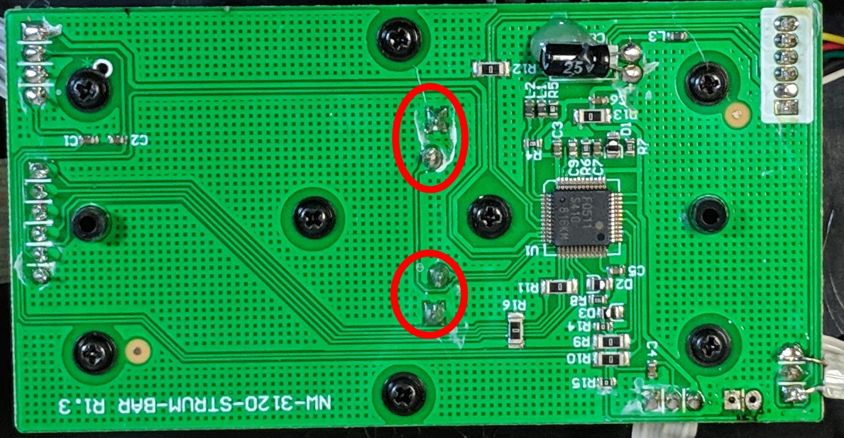
In this case, there are two grounds that will be shorted together, so with the multimeter, you should be able to work out which pins are ground, by testing a pin from each switch, and working out which ones are shorted together by it beeping.
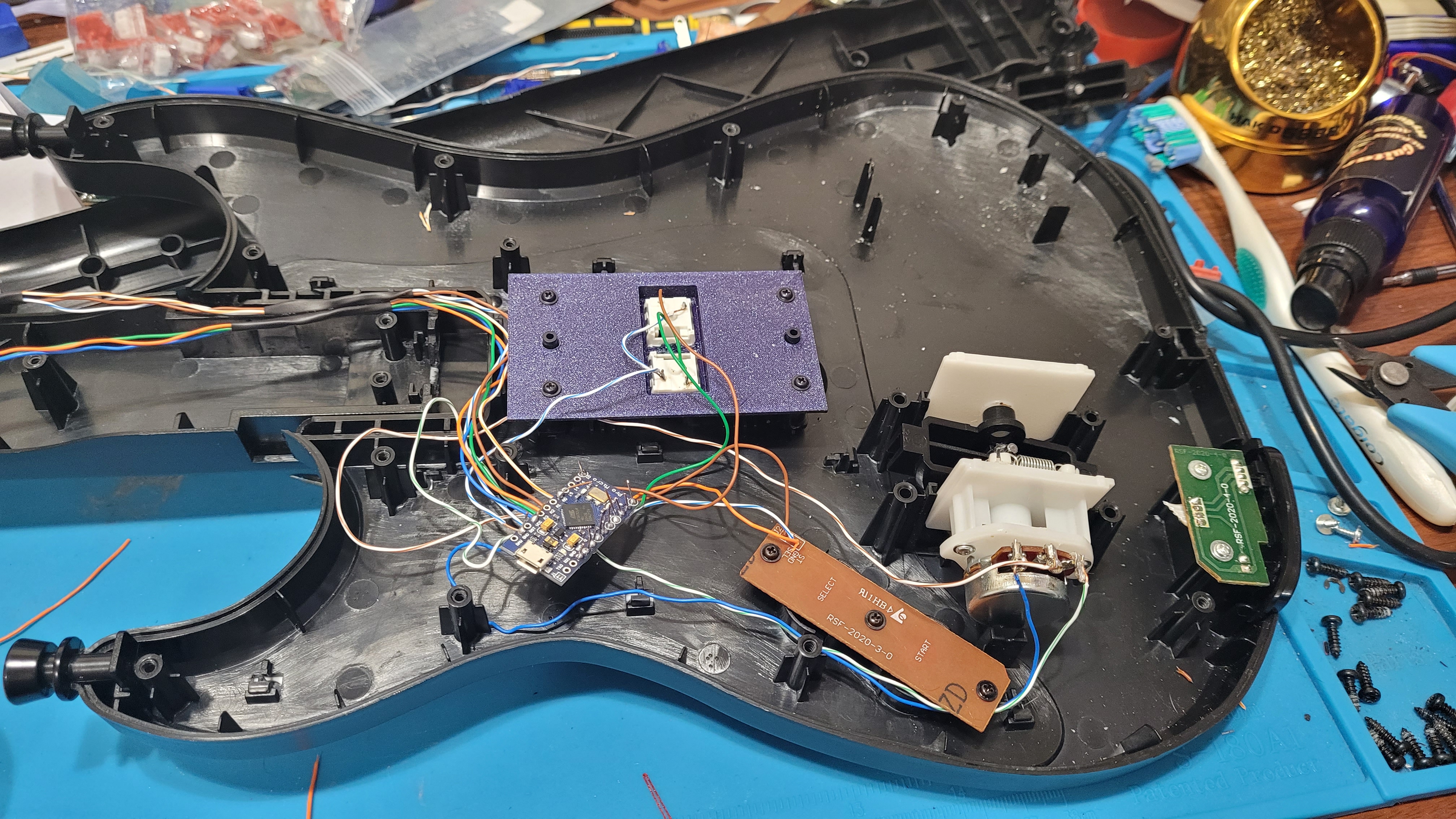
Note that you can also choose to replace the original PCB with a 3D printed strum switch holder. If you want to go that route, there are some designs around for various guitars. The image at the beginning of this guide shows how this would look.
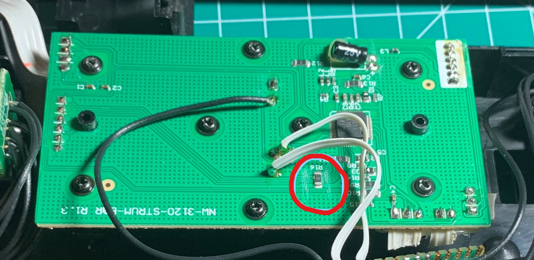
When the strums are part of the main board you will need to cut the traces or you will have phantom inputs as your signal will still be traveling through the motherboard. (this is when your strum switches constantly input and you likely cannot autobind inputs in the configurator) You will need to take a knife and cut any traces that connect to the strum switches. In the picture below, the person did not cut many traces as they knew which ones were causing phantom inputs. Cutting extra traces is not going to affect your arduino guitar, as none of the traces are used except the one that connects the two grounds of the switches together. Even if you accidentally cut that trace, you will be able to connect the grounds again with a little extra wire.
Guitar Hero World Tour neck
The world tour slider bar originally used a single wire to connect between the bar and the main PCB. This caused a lot of problems, as the format of data being sent over this wire is not optimal for speed, and it limits the combinations of frets we can read from the slider bar. To combat this, we bypass the chip generating this data, and opt to use a dedicated touch sensor chip, the MPR121, to handle reading from the slider bar and sending us data in a format that we can easily use.
-
Cut the traces indicated with red lines in the following image on your Slider bar PCB. You can also opt to just desolder U2 if you prefer.

-
Solder each of the circled vias on the WT Slider bar PCB to its own channel on the MPR121. It is recommended to use channels 0-4 for the slider bar, as the MPR121 requires assigning touch pads first before other pins.

-
For the frets, follow the traces between the fret contacts. The ground wire traces will connect to all of the fret contacts, whereas a fret trace will lead to a single fret contact. At the end of this guide, there are some images for known neck pinouts. If using the multimeter, test between the fret wire and the ground wire, and the multimeter should beep when the fret is pressed.
-
Connect the common grounds to a ground pin on the MPR121.
-
Connect each fret to its own unused channel on the MPR121.
-
Hook up VCC (marked as 3.3V) and GND (marked as GND) to the microcontroller. Note that this means you need to use a 3.3V power pin on your microconroller, so if your microcontroller only has 5V power pins you will need a voltage regulator.
-
Hook up SDA and SCL to the microcontroller
Microcontroller SDA (D) SCL (C) Pro Micro, Leonardo, Micro 2 3 Uno A4 A5 Mega 20 21
GH5 guitar neck (Standard)
-
Hook up VCC (marked as V or VCC) and GND (marked as GND or G) to the microcontroller
-
Hook up SDA (Marked as D) and SCL (marked as C) to the microcontroller
Microcontroller SDA (D) SCL (C) Pro Micro, Leonardo, Micro 2 3 Uno A4 A5 Mega 20 21
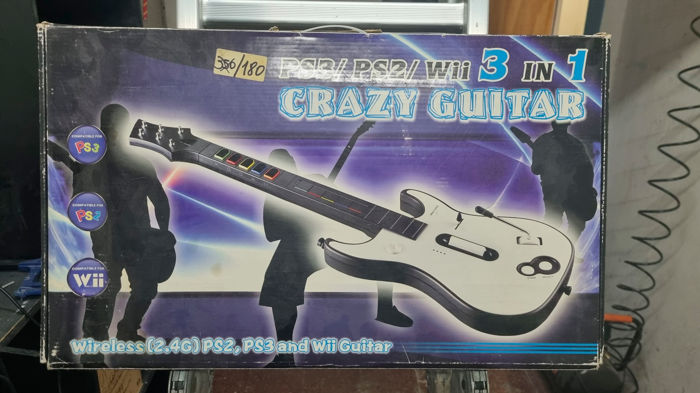
Crazy guitar neck (Standard)
-
Hook up VCC, GND, SCL and SDA pins to your microcontroller. Note that this is one of the few I2C devices that works perfectly fine on 5v.
-
Hook up SDA (Marked as D) and SCL (marked as C) to the microcontroller
Microcontroller SDA (D) SCL (C) Pro Micro, Leonardo, Micro 2 3 Uno A4 A5 Mega 20 21
GH5 / Crazy guitar frets (Direct, lower latency)
- If you wish to bypass the neck connector for your frets, you can wire the frets directly to the microcontroller or use an MPR121 to avoid needing to run more wires. The MPR121 replaces the entire slider bar PCB and handles both the slider pads and the frets.
- For direct mode, run a wire from each fret pin to a pin on the microcontroller, and connect the ground pin on the fret PCB to the microcontroller's ground pin.
GH5 / Crazy guitar frets (MPR121, Low Latency Frets with 4 pins)
-
In some cases, you may want to poll frets directly, but you still wish to use a neck connector that does not have enough pins to connect the frets. You can get around this by using an MPR121.
-
Cut the traces going from the main chip to the pads on the slider PCB.
-
Solder each via on the Slider bar PCB to its own channel on the MPR121. It is recommended to use channels 0-4 for the slider bar, as the MPR121 requires assigning touch pads first before other pins.
-
For the frets, follow the traces between the fret contacts. The ground wire traces will connect to all of the fret contacts, whereas a fret trace will lead to a single fret contact. At the end of this guide, there are some images for known neck pinouts. If using the multimeter, test between the fret wire and the ground wire, and the multimeter should beep when the fret is pressed.
-
Connect the common grounds to a ground pin on the MPR121.
-
Connect each fret to its own unused channel on the MPR121.
-
Hook up VCC (marked as 3.3V) and GND (marked as GND) to the microcontroller. Note that this means you need to use a 3.3V power pin on your microconroller, so if your microcontroller only has 5V power pins you will need a voltage regulator.
-
Hook up SDA and SCL to the microcontroller
Microcontroller SDA (D) SCL (C) Pro Micro, Leonardo, Micro 2 3 Uno A4 A5 Mega 20 21
Programming
- Start Santroller with your microcontroller plugged in.
- Set the Input Type to Directly Wired
- Click
Configure - Click on
Controller Settings - Set
Emulation TypetoController - Set the
Controller Typebased on the game you want to play. Windows Controller Modecan be set based on your preferences. Note that this is only for Windows, no other operating systems or consoles will be affected by this option.XInput- This works more natively on windows, and most games will automatically bind controls.HID- This uses HID on windows, which means games won't automatically bind controls, but HID is polled a bit more efficiently in games like Clone Hero.
- If you would like to adjust settings related to polling, click on
Controller Poll Settings - If you would like to use
Queue Based Inputsyou can turn that on here. This puts any buttons you press into a queue, and sends them out to the PC as fast as USB allows. This means that the controller will process your inputs at a faster poll rate than 1ms (the fastest rate USB allows) and then the PC will be sent your inputs at a 1ms rate. - Set the Poll Rate to your preferred setting. 0 sends data as fast as possible, any other number polls inputs at that speed.
- Debounce can be adjusted here. Debounce is necessary as button inputs are noisy. When you click a button, it will often bounce and send multiple presses, which some games may percieve as you clicking the button multiple times, which can result in dropped sustains. When you set debounce to a value, the signal ignores any release inputs for that time frame, so if you for example set it to 1ms, then the button input will be on for a minimum of 1ms, and only after that will the release be processed. This has the effect of stretching out the button press to at least 1ms, which ignores any bouncing in that timeframe.
- Combined strum debounce shares the debounce timeframe between both strums. This means that if you set the strum debounce to 1ms and strummed down, both strum up and down inputs are ignored over that 1ms timeframe. This helps avoid extra strum inputs when your strum switch rebounds after being released.
- Now you can start setting up your inputs. To keep this information relevant, it is grouped by function.
Frets, strum and other buttons
- Click on the button you want to configure, and make sure the
Input Typeis set toDigital Pin Input. - Make sure
Pin Modeis set toPull Up. - Click on the
Find Pinbutton, and then press the button on the guitar. If you have wired everything correctly, the tool should detect the pin and the icon for that button should now light up whenever the button is pressed.
RB Solo Frets (Combined)
In this example we will use the green solo fret, but you can substitute the fret for the other colours to set the rest of the frets up.
- Click on the green solo fret.
- Set the
Input TypetoShortcut - Set the next
Input TypetoDigital Pin Input - Make sure
Pin Modeis set toPull Up. - Click on the first
Find Pinbutton, and then press the normal green fret button. - Hold the green fret and then press the second
Find Pinbutton. While holding the green fret, press the solo green fret. This should then detect the solo input, and you can release both buttons. At this point, the icon for the green solo fret should light up when it is pressed.
Start + Select to Home
- Click on the home / Xbox / PS button.
- Set the
Input TypetoShortcut - Set the next
Input TypetoDigital Pin Input - Make sure
Pin Modeis set toPull Up. - Click on the first
Find Pinbutton, and then press the start button on the guitar. If you have wired everything correctly, the tool should detect the pin. - Click on the second
Find Pinbutton, and then press the select button on the guitar. If you have wired everything correctly, the tool should detect the pin and the icon for the home button should now light up whenever both start and select is pressed.
Joystick
- Click on D-pad Left, and set the
Input TypetoAnalog Pin Input. - Set
TypetoJoystick Negative - Click on
Find Pinand move the joystick left or right - Adjust the threshold so that the D-pad Left icon lights up when you have pushed the Joystick far enough to the left. This means you can adjust how sensitive you want your joystick to be.
- You can do the same for D-pad right, however, set the
TypetoJoystick Positiveinstead. - If you wish to also map joystick up and down, click
Add Settingand add another Strum Up and Strum Down input. Then you can follow the above instructions again, only using negative for up and positive for down, and when detecting the pin, move the joystick up and down instead.
Whammy
- Click on the whammy, and make sure the
Input Typeis set toAnalog Pin Input. - Click on the
Find Pinbutton, and then press on the whammy. If you have wired everything correctly, the tool should detect the pin and theOriginal Valuevalue should change when you push on the whammy. - Click on
Calibrate. - Release the whammy bar and click
Next. - Push the whammy all the way in, and click
Next - Release the whammy again, and click
Next. If your whammy is noisy, you can push it in a tiny bit, and the zero position will be set to this location, which will make sure that the whammy is always considered released when it is released.
Pickup Selector
- Click on the pickup selector, and make sure the
Input Typeis set toAnalog Pin Input. - Click on the
Find Pinbutton, and then move the pickup selector. If you have wired everything correctly, the tool should detect the pin and theOriginal Valuevalue should change when you move the pickup selector. - If the
Original Valueof the pickup selector decreases as you increase the notch position on your guitar, turn onInvert. - Set the pickup selector to the second position
- Drag the slider for
Notch 2 Valueso that the current notch isNotch 2. - Set the pickup selector to the third position and then move the slider for
Notch 3as detailed above. - Repeat this for the other notches. After this, the current notch should reflect the status of the pickup selector.
Digital Tilt
- Click on Tilt, and make sure the
Input Typeis set toDigital Pin Input. - Make sure
Pin Modeis set toPull Up. - Click on the
Find Pinbutton, and then tilt your guitar. If you have wired everything correctly, the tool should detect the pin and the tilt icon should light up whenever you tilt the guitar. - If you are using a SW520D based tilt sensor, some versions of this sensor will have an inverted output. You can turn on the
Invertoption to correct this.
Analog Tilt
- Click on Tilt, and make sure the
Input Typeis set toAnalog Pin Input. - Click on the
Find Pinbutton, and then tilt your guitar. If you have wired everything correctly, the tool should detect the pin and the tiltOriginal Valuevalue should change as you tilt your guitar. - Click on
Calibrate - Hold your guitar in its resting position, and then click
Next - Tilt the guitar up, and then click
Next - Tilt your guitar up a little bit and then click
Next. Values below this position will be zeroed.
ADXL345 or MPU-6050 or LIS3DH based Tilt
- Click on
Add setting - Add an
Accelerometer - Click
Save - Click on Tilt, and make sure the
Input Typeis set toAccelerometer Input. - Click on
Calibrate - Hold your guitar in its resting position, and then click
Next - Tilt the guitar up, and then click
Next - Tilt your guitar up a little bit and then click
Next. Values below this position will be zeroed. With the adxl, you can increase the deadzone to help counteract strumming or shaking activating tilt. - Adjust the
Low Pass Filter. This value controls how new value from the ADXL are filtered, a value closer to 0 will result in a sensor that won't respond to a shake or strumming, but if you decrease it too much the sensor will have a decreased responsiveness. If you set it closer to 1, then the sensor will be very responsive but it will also pick up any tiny vibrations as well. From testing a value of 0.05 seemed like a good place to start.
MPR121
- Click on
MPR121 Settings - Enable the Peripheral
- Set the SDA and SCL pins that you have used.
- Set the
MPR121 Capacitive Touch Pad Countbased on the number of touch pads you are using. For a normal slider bar, this should be 5, or if you aren't using a slider bar set this to 0. - Click
Save
World Tour Slider Bar
- Click on Add Setting, and add a
Slidersetting - Set the
Input TypetoMPR121 Input - Click
Save Settings. Note that everything else needs to be configured before you can do this. - Set the channels based on your wiring. The configuration will update live, so if you are unsure which via maps to which slider pad, you can just work through the channels and assign things to the correct pads by touching each pad and working out which channel is which.
- Go to each fret, and set its
Input TypetoMPR121 Input. - Set the channel based on your wiring. If you are unsure which channel you used, you can just walk through each channel and work out which one was used, as the status of the MPR121 will update live as you press and release frets.
GH5 Neck (Standard wiring)
- The GH5 neck puts inputs over a single set of pins. This does add a bit of latency to the frets, but if you want the simplest wiring, you can keep the frets connected to the neck.
- Click on Add Setting, and add a
GH5 Neck Inputssetting - Set the SDA and SCL pins to the pins you used when you wired up the neck.
- If you would like to map the slider bar to the standard frets, you can enable "Slider to frets". Note that if you are using
Rock Bandmode, the tap bar is automatically mapped to the solo frets. - Click on
enablefor each of the frets.
Crazy Guitar Neck (Standard wiring)
- The Crazy Guitar neck puts inputs over a single set of pins. This does add a bit of latency to the frets, but if you want the simplest wiring, you can keep the frets connected to the neck.
- Click on Add Setting, and add a
Crazy Guitar Neck Inputssetting - Set the SDA and SCL pins to the pins you used when you wired up the neck.
- If you would like to map the slider bar to the standard frets, you can enable "Slider to frets". Note that if you are using
Rock Bandmode, the tap bar is automatically mapped to the solo frets. - Click on
enablefor each of the frets.
GH5 / Crazy Guitar (MPR121 Mode)
1. If you wish to have better latency frets with these necks, you can replace the slider bar controller with an MPR121, which will give you low latency but will still use the same amount of wires.
2. Click on Add Setting, and add a `Slider` setting
3. Set the `Input Type` to `MPR121 Input`
4. Click `Save Settings`. Note that everything else needs to be configured before you can do this.
5. Set the channels based on your wiring. The configuration will update live, so if you are unsure which via maps to which slider pad, you can just work through the channels and assign things to the correct pads by touching each pad and working out which channel is which.
6. Go to each fret, and set its `Input Type` to `MPR121 Input`.
7. Set the channel based on your wiring. If you are unsure which channel you used, you can just walk through each channel and work out which one was used, as the status of the MPR121 will update live as you press and release frets.
- If you do not want to hook an input up, click the
Removebutton to the right on that input. - Once everything is configured correctly, the
Save Settingsbutton should be clickable and you can hit that button to write your config to the guitar. It is now ready.