Setting up an Adaptor for a PS2 Controller
Supplies
-
A microcontroller
- Raspberry Pi Pico users: this legacy release does not support Pico boards. Use the currently supported Santroller tooling at santroller.com.
-
SparkFun Pro Micro (5V or 3.3V)
- The 3.3V version is easier to use with Wii and PS2 controllers. The 5V version requires voltage conversion for 3.3V peripherals.
-
Arduino Micro
-
Arduino Leonardo
-
Arduino Uno R1, R2, or R3
- The board must have the ATmega16U2 USB controller. Uno clones that use a CH340 USB chip are not supported.
-
Arduino Mega 1280, Mega 2560, or Mega ADK
-
For any 5v microcontrollers, you will need a 3.3v voltage regulator.
-
PS2 Controller socket
-
2x 1kΩ Resistor
-
Some Wire
-
A Soldering Iron
Be careful that you don't ever provide 5v power to any pins on the PS2 Controller. While some people have done this successfully and just use their controllers with 5v, I can't recommend this approach as the controllers are really designed for 3.3v, so it may damage them slowly over time.
Steps
-
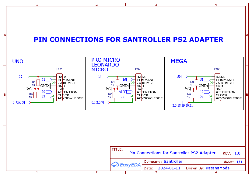
Connect pins according to the below table.
For beginners we provide a recommended pinout below for each microcontroller. These pinouts are the same pinouts that are used on the old Ardwiino firmware, so if you have an old device, this is the pinout it will be using.
Note that this image is of the plug on the controller, and not looking at the socket. Make sure you have your wiring in the right order.
| Microcontroller | SCK / Clock / Blue | MOSI / Command / Orange | MISO / Data / Brown | Acknowledge / Green | Attention / Yellow |
|---|---|---|---|---|---|
| Pro Micro, Leonardo, Micro (Recommended) | 15 | 16 | 14 | 7 | 10 |
| Uno (Recommended) | 13 | 11 | 12 | 2 | 10 |
| Mega (Recommended) | 52 | 51 | 50 | 2 | 10 |
| Pro Micro, Leonardo, Micro (Advanced) | 15 | 16 | 14 | 0, 1, 2, 3 or 7 | Any |
| Uno (Advanced) | 13 | 11 | 12 | 2 or 3 | Any |
| Mega (Advanced) | 52 | 51 | 50 | 2, 3, 18, 19, 20 or 21 | Any |
- Connect a 1kΩ resistor between MISO and 3.3v.
- Connect a 1kΩ resistor between Acknowledge and 3.3v.
- Connect the 3.3v pin on the ps2 controller to the 3.3v pin on your microcontroller. For microcontrollers that can output 3.3v natively, you can hook this straight up to 3.3v, but for a 5v only board like the Pro Micro 5v you will need to use a 3.3v voltage regulator to get a stable 3.3v voltage.
- Connect the gnd pin on the PS2 controller to the gnd on your microcontroller.
Programming
- Start Santroller with your microcontroller plugged in.
- Set the Input Type to
PS2 Adapter - Hit Configure
- Click on
Controller Settings - Set
Emulation TypetoControllerfor controllers, orFortnite Festivalif you want to emulate a keyboard forFortnite Festival - Set the
Controller Typebased on the game you want to play. Windows controller modecan be set based on your preferences. Note that this only affects windows, a controller in XInput mode will use the correct mode on a console, and will automatically use HID mode on Linux and macOS.XInput- This works more natively on windows, and most games will automatically bind controls.HID- This uses HID on windows, which means games won't automatically bind controls, but HID is polled a bit more efficiently in games like Clone Hero.
- If you would like to adjust settings related to polling, click on
Controller Poll Settings - If you would like to use
Queue Based Inputsyou can turn that on here. This puts any buttons you press into a queue, and sends them out to the PC as fast as USB allows. This means that the controller will process your inputs at a faster poll rate than 1ms (the fastest rate USB allows) and then the PC will be sent your inputs at a 1ms rate. - Set the Poll Rate to your preferred setting. 0 sends data as fast as possible, any other number polls inputs at that speed.
- Debounce can be adjusted here. Debounce is necessary as button inputs are noisy. When you hit a button, it will often bounce and send multiple presses, which some games may percieve as you hitting the button multiple times, which can result in dropped sustains. When you set debounce to a value, the signal ignores any release inputs for that time frame, so if you for example set it to 1ms, then the button input will be on for a minimum of 1ms, and only after that will the release be processed. This has the effect of stretching out the button press to at least 1ms, which ignores any bouncing in that timeframe.
- Combined strum debounce shares the debounce timeframe between both strums (only available on guitars). This means that if you set the strum debounce to 1ms and strummed down, both strum up and down inputs are ignored over that 1ms timeframe. This helps avoid extra strum inputs when your strum switch rebounds after being released.
- Click on
PS2 Controller Inputs - Set the Acknowledge and Attention pins
- Hit Save.
- You can now calibrate your inputs. If your controller is already plugged in it should be detected and show only those inputs, but you can use the
Wii Inputs to display belowdropdown to specify the controller you want to configure.- Joysticks
- Hit the
Calibratebutton and then move the stick all the way left / up - Hit
Nextand then move the stick all the way right / down - Hit
Nextand then move stick a little bit away from the center. This sets the deadzone, and any inputs closer to the center from this position will be ignored, which helps with noisy sticks.
- Hit the
- Whammy
- Click on
Calibrate. - Release the whammy bar and hit
Next. - Push the whammy all the way in, and hit
Next - Release the whammy again, and hit
Next. If your whammy is noisy, you can push it in a tiny bit, and the zero position will be set to this location, which will make sure that the whammy is always considered released when it is released.
- Click on
- Joysticks